Design of a radome –
Initial considerations before building a radar housing.
Radar antennas are often placed behind a housing to protect them. Due to the special properties of radar waves and effects inherent to the measurement method, developing a radome is very complex process. However, in this article we would like to give you some initial details on radome design. We will use sample values to show you which aspects must be taken into account in the design. This rough overview is no substitute for the calculations and tests required to produce a reliable radome.
What does a radar sensor consist of?
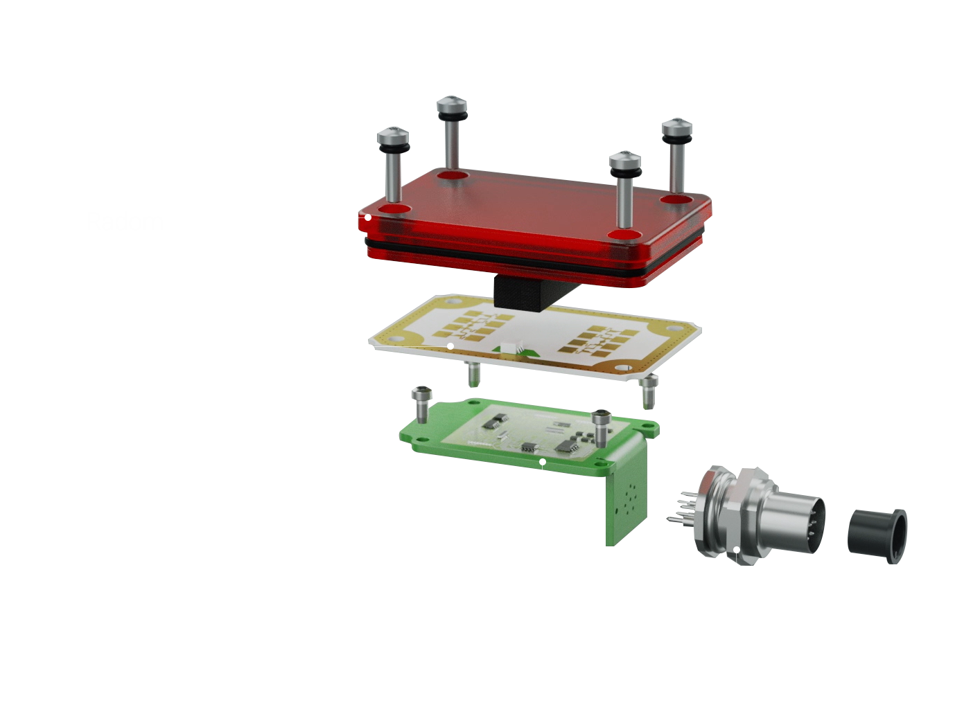
Radar sensor systems have different components:
- the microwave component with an antenna structure (radar front end)
- components for signal processing (depending on the system level)
- optional elements: a radome, housing, lens, or component carrier

Figure 1: basic components of a radar system. (image source: InnoSenT)
The actual radar detection takes place in the front end (RFE), because the antenna sends and receives electromagnetic pulses here. The information attained is forwarded by the front end for signal processing. Lenses are also sometimes placed in front of the antenna to focus the radar beam. One example of a system that uses this design is the iSYS-6030 from InnoSenT.
Step 1: why do I need a radome?
The sensors are generally also equipped with a housing to protect the radar antenna and the electronic components. This is meant to protect the front end from external influences such as weather-related damage or vandalism. But the housing may also be used for appearances. Radar penetrates various materials. For this reason, the sensors can also be concealed in an existing product design. One example of this is the integration of a radar into the bumper of a car or a touchless switch system in a coffee machine.
Instead of a protective housing, radar experts refer to a ‘radome’. The word is made up of the terms ‘radar’ and ‘dome’ and describes the dome-shaped cover that is often attached to large, stationary radar systems used in aeronautics and maritime navigation.
But sensors and systems also benefit from radomes in industrial usage or commercial applications. They protect the antenna function from mechanical wear, dirt, scratches, or chemical damage. The design of the housing must be optimally adapted to the antenna design and radar characteristics. This starts with selecting the appropriate material.
Step 2: the selection of material
The material plays a key role. But not everything is equally suitable for the design of a radome. When radar waves hit an object or person, the properties of the surface at the point of contact influences the propagation and reflection of electromagnetic waves. Some materials are easy to penetrate, while others reflect the radar beam or absorb it too much.
The following table shows the behaviour of radar waves when they hit various materials. Taking these properties into account, it is possible to select the appropriate material.
| MATERIAL | ABSORPTION | REFLECTION | WAVE PENETRATION |
|---|---|---|---|
| Metal | none | straight-on incidence: complete; diagonal angle of incidence: refraction and partial reflection possible | virtually impossible, only millimetre fractions penetrate into the surface (skin effect) |
| Wood (depending on humidity) | medium to high | low | low |
| Water | very high | depending on the angle of incidence: partial or complete reflection possible | none, due to absorption |
| Foams (e.g. polystyrene, roofmate) | low | none | very good |
| Plastics | low to high (depending on material and thickness) | low tho high (depending on material, thickness and distance) | low to high (depending on material, thickness and distance) |
Table 1 Overview of absorption, reflection, and penetration of radar waves.
A radome is intended to protect the antenna, but it must allow the transmitted and received signal to pass with as little loss of signal strength as possible. Metal is very easy to detect due to its reflectiveness, but is unsuitable for use in a radome, as it blocks the signal. Wooden housings are also problematic, as they only have a limited ability to allow pulses to pass through them.
Foams such as polystyrene, on the other hand, are very suitable for covering the front end. They can even be placed directly on the antenna. However, one challenge is their low stability and sensitivity to chemicals, which can reduce the protective effect of the housing.
Not all plastics are the same.
Radar waves penetrate plastics. This makes them the best choice for the radome designs. However, here too, various parameters have to be taken into account, because plastics vary enormously. And they may be better or worse suited for the design depending on their properties.
If the plastic also contains other substances, such as carbon in the case of black plastics, this can also cause measurement losses.
Coatings that are often applied to plastics can also negatively impact penetration. Accumulated water due to rough or uneven surfaces can affect detection.
Dimensions & orientation of a radome
Now that you have probably opted for a plastic radome, more considerations follow. In addition to the type of material, the exact positioning and shape must also be taken into account in the design of a protective housing.
In order not to impede the radar’s functionality, you must always observe these three aspects in its design:
- the position: distance and orientation of the radome with respect to the antenna
- the material thickness
- the shape
These factors impact the reflection and absorption. They are the factors determining the quality with which the sensor sends and receives signals. The thicker the material and the shorter the distance, the less radar waves penetrate the plastic.
Step 3: the correct positioning.
The antenna design is decisive for the directivity and design of the radar’s detection range. Positioning a radome in front of the antenna affects how the radar waves spread. Homogeneous damping is important in order not to cause any interference with the transmission and reception of the electromagnetic waves. In practice, this means there must be a uniform distance between the radome and antenna at any given point (parallel arrangement). Even slight deviations, such as a small notch on the underside of the radome, alter radar wave propagation.
Slanted radomes also adversely affect correct reflection. This also applies to rounded ends, protrusions, reinforcements, or grooves in the material (see figure).

Caption: The positioning is wrong on the left. The radome has an uneven surface and is not positioned parallel to the antenna. The right picture shows the correct positioning of a radome, with even distances. (image source: InnoSenT)
Step 4: how do I determine the correct distance?
Physical rules regarding radar technology must be taken into account. The following example for 24 GHz sensors illustrates this.
- The wave propagation is least impeded when they hit the radome exactly at half a wavelength (or a multiple of it).
- This means you must position the cover parallel the antenna surface (wave centre) at a distance of (or a multiple of it).
- With a centre frequency of 24,125 GHz (with half a wavelength of approximately 6.2 mm), the optimum distance is approx. 6.2 mm.
Step 5: find out the right material thickness
The material thickness can also be determined in a similar way to the correct distance. Because the radar waves must enter and exit within half of the wavelength in order to reduce any disturbance of their propagation to a minimum. This means you must also select the material thickness suitable for half of the wavelength.
However, with the material thickness, you also have to take into account the material substance – or more specifically, how the radar wave is modified by the type of material when the radar enters/penetrates the radome. The adaptation is made based on the researchable conductivity (referred to as dielectric function ε or primitivity) of the selected material. Because the wavelength is shortened by the penetration. An adjustment must be made by the factor .
With plastics, the dielectric constant is in theory between three and four. However, due to the many variations of the material, this number may, in fact, vary greatly in practice, so it is recommended to make an exact determination.
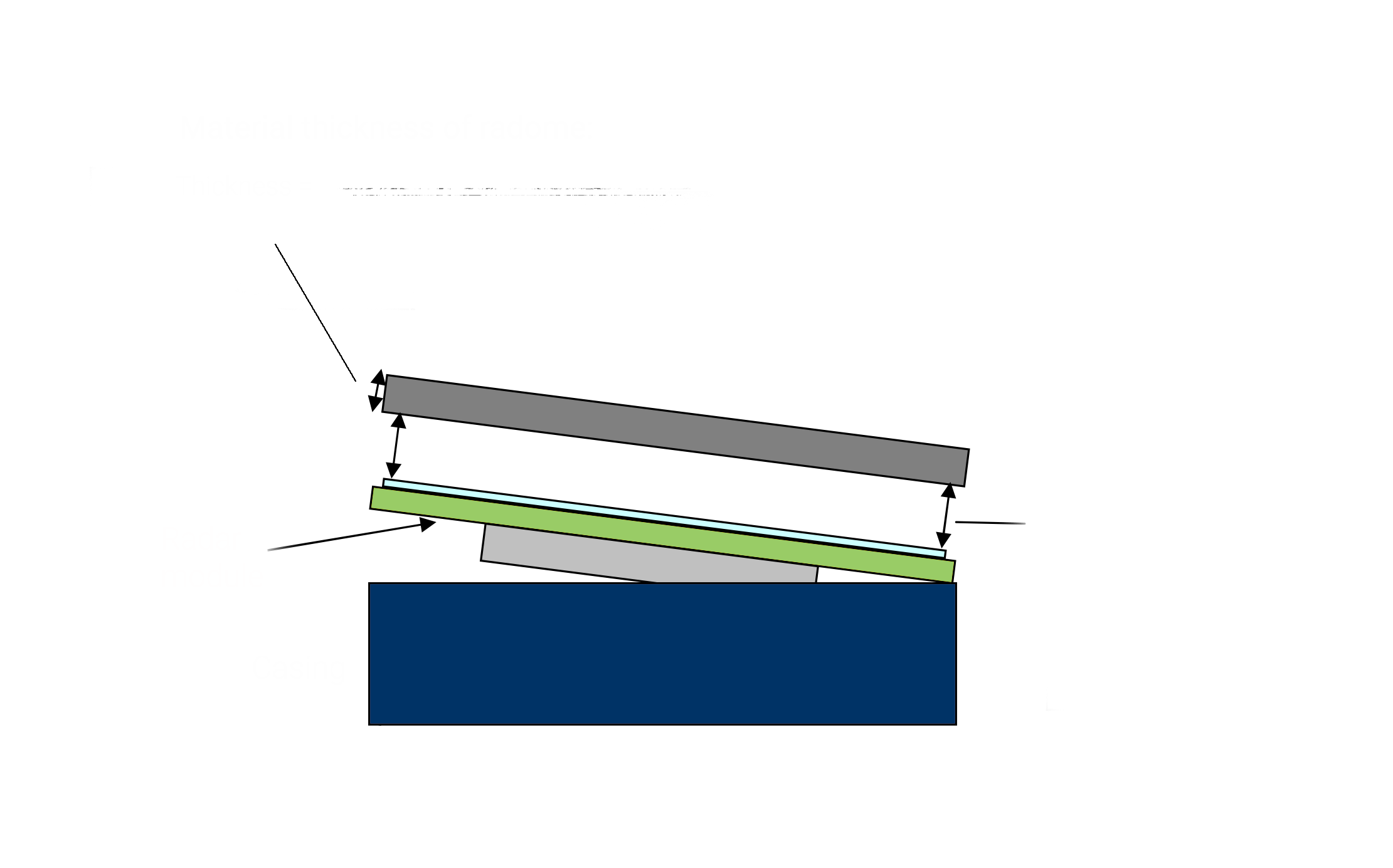
Using a fictitious example (see figure), we still carry out a calculation to illustrate this, nonetheless. For this purpose, we will simply take the mean value of 1.5.
The formula can now be used to determine the material thickness. Going off the given values, the thickness is found by dividing the wavelength λ of 24.125 GHz by 2 (result: 6.2 mm) and subsequently dividing that by the root of the shortening factor of 1.5 (dielectric constant), resulting in a material thickness of approximately 4 mm.

Figure 3: example calculation for the correct material thickness of a radome. (image source: InnoSenT)
Theory vs practice
The considerations, planning, and design of the radome can take a long time depending on the use case. Because determining the necessary values as well as the product design and, for instance, how to integrate the system into a vehicle can be simple or very complex.
For other radar applications, especially very simple use cases in the low-cost range, a radome can easily be designed based on rough estimates. For simple motion detection, for instance to open a door, it suffices to use approximate data for the calculations without significantly impacting the sensor’s functionality. For designing a radome made of plastic, our radar experts recommend a general material thickness of 2 mm and a distance of 6 mm. In order to achieve optimised performance, a more precise and complex calculation is required here.
In order to prevent rejects and restrictions in radar detection, our radar experts will be happy to advise you on designing a suitable radome.
Share this Content
Get this technology on your radar
Information on this advanced sensor technology
The demand for sensors is increasing due to trends such as digitalisation, automation in industry & logistics, smart homes & cities, and autonomous driving. But the development and integration of radar units is a complex topic, and the technical terms and functions raise many questions for users. Our radar experts have put together comprehensive information to help you get started in the world of radar.


